Showing posts with label Security. Show all posts

Tuesday, June 9, 2015

Network Security Attacks and Defence

Network security

Network security involves the authorization of access to data in a network, which is controlled by the network administrator. Users choose or are assigned an ID and password or other authenticating information that allows them access to information and programs within their authority. Network security covers a variety of computer networks, both public and private, that are used in everyday jobs conducting transactions and communications among businesses, government agencies and individuals. Networks can be private, such as within a company, and others which might be open to public access. Network security is involved in organizations, enterprises, and other types of institutions. It does as its title explains: It secures the network, as well as protecting and overseeing operations being done. The most common and simple way of protecting a network resource is by assigning it a unique name and a corresponding password.


Types of attacks include:


Active

      1.  Denial-of-service attack (DoS)

      2.  Spoofing

      3.  Man in the middle

      4.  ARP poisoning
      5.  DNS Spoofing

      6.  Smurf attack

      7.  Buffer overflow

      8.  Heap overflow

      9.  Format string attack

      10.  SQL injection
      11. Cyber attack

 Passive
      1. Network

             a. Wiretapping

             b. Port scanner

             c. Idle scan
 

Denial-of-Service Attack (DoS)

 Denial of Service (DoS) attacks are among the most feared threats in today's cybersecurity landscape. Difficult to defend against and potentially costly, DoS attacks can cause outages of web sites and network services for organizations large and small. DoS attacks can also be lucrative for criminals, some of whom use these attacks to shake down businesses for anywhere from thousands to millions of dollars. 

DoS attack is used as a distraction to funnel attention and resources away while a targeted breach attack is being launched. Anonymous used that technique in a major 2011 attack that ultimately led to the theft of over 12 million customers' credit card data.


 DoS vs DDoS


The most easily executed type of DoS attack is one that is launched from a single origin. In this attack, a single machine somewhere on the Internet issues a barrage of network requests against a targeted victim machine. The requests themselves can take a variety of forms – for example, an  attack might use ICMP Flooding via ping requests, or HTTP requests against a web server.

In a DDoS attack, the incoming traffic flooding the victim originates from many different sources – potentially hundreds of thousands or more. This effectively makes it impossible to stop the attack simply by blocking a single IP address; plus, it is very difficult to distinguish legitimate user traffic from attack traffic when spread across so many points of origin.

How a Denial of Service Attack Works

The simple approach to DOS is to flood a server with a large amount of pointless traffic. This gives the server far too much to deal with. Bandwidth escalates, memory is exhausted and ordinary users can’t get a connection to the server.
But actually maxing out a server can be quite difficult, even with a large number of computers opening up as many connections as they can. As such, attackers have come up with a way to magnify the effect by using fake IP addresses.
Using fake IPs, the same process can be carried out by one computer, a botnet that’s controlled by one master or, as with Operation Payback, a group of people working together.
Here’s what happens.

  1. The attacking machine sends a SYN packet to the server. However, it makes it appear to come from somewhere else.
  2. The server then responds with a SYN/ACK packet, but there’s no response – the sender address was fake.
  3. The server continues to wait for a reply, keeping the connection open and in its memory until it times out.
The server keeps a bunch of useless connections open, losing more and more memory to the attack and eventually becoming crippled.
The strategy is actually fairly successful. It has slowed or crashed some prominent sites.
However, companies have become wise to DDOS attacks and have begun to take some precautions.

Risks Associated with Denial of Service Attacks

Denial of Service attacks are centered around the concept that by overloading a target’s resources, the system will ultimately crash. In the case of a DoS attack against a web application, the software is overloaded by the attack and the application fails to serve web pages properly. To crash a web server running an application, a DoS threat attacks the following services:

  • Network bandwidth
  • Server memory
  • Application exception handling mechanism
  • CPU usage
  • Hard disk space
  • Database space
  • Database connection pool

Can a DDoS be stopped ?

Let's start with the bad news: It is very difficult to defend against a sophisticated DDoS attack launched by a determined adversary.

There are several ways to defend against a DDOS attack. None can guarantee prevention, but the website owner does have options:

  1. Filtering: Routers at the edge of the network can be trained to spot and drop DDOS connections, preventing them from slowing the network or the server.
  2. Moving: If the attack is pointed at a specific IP address, the site’s IP can be changed. This is what the White House did before a nasty computer virus tried to DDOS its site.
  3. Blackholing: A host may simply “blackhole” a site that is being DDOSed, directing all traffic to it to an address that doesn’t exist. This is normally a last resort.
In addition, many companies sell anti-DDOS applications that detect and block attacks.
The only sure-fire way to end a DDOS attack is to wait it out. Most attacks don’t last very long because those with botnets don’t wish to expose their network for too long, and group attacks can’t hold their cohesion forever. Though it may take a few days, the attack will cease of its own accord.
 

Spoofing

A spoofing attack is when a malicious party impersonates another device or user on a network in order to launch attacks against network hosts, steal data, spread maleware or bypass access controls. There are several different types of spoofing attacks that malicious parties can use to accomplish this. Some of the most common methods include IP address spoofing attacks, ARP spoofing attacks and DNS server spoofing attacks.


ARP Spoofing/ Poisoning

 ARP Spoofing/ Poisoning is a technique whereby an attacker sends fake ("spoofed") Address Resolution Protocol (ARP) messages onto a Local Area Network. Generally, the aim is to associate the attacker's MAC address with the IP address of another host (such as the default gateway), causing any traffic meant for that IP address to be sent to the attacker instead.

ARP spoofing may allow an attacker to intercept data frames on a LAN, modify the traffic, or stop the traffic altogether. Often the attack is used as an opening for other attacks, such as denial of service, man in the middle, or session hijacking attacks.
The attack can only be used on networks that make use of the Address Resolution Protocol (ARP), and is limited to local network segments.


DNS Server Spoofing Attacks

The Domain Name System (DNS) is a system that associates domain names with IP addresses. Devices that connect to the internet or other private networks rely on the DNS for resolving URLs, email addresses and other human-readable domain names into their corresponding IP addresses. In a DNS server spoofing attack, a malicious party modifies the DNS server in order to reroute a specific domain name to a different IP address. In many cases, the new IP address will be for a server that is actually controlled by the attacker and contains files infected with malware. DNS server spoofing attacks are often used to spread computer worms and viruses.

Spoofing Attack Prevention and Mitigation

There are many tools and practices that organizations can employ to reduce the threat of spoofing attacks. Common measures that organizations can take for spoofing attack prevention include:

  • Packet filtering: Packet filters inspect packets as they are transmitted across a network. Packet filters are useful in IP address spoofing attack prevention because they are capable of filtering out and blocking packets with conflicting source address information (packets from outside the network that show source addresses from inside the network and vice-versa).
  • Avoid trust relationships: Organizations should develop protocols that rely on trust relationships as little as possible. It is significantly easier for attackers to run spoofing attacks when trust relationships are in place because trust relationships only use IP addresses for authentication.
  • Use spoofing detection software: There are many programs available that help organizations detect spoofing attacks, particularly ARP spoofing. These programs work by inspecting and certifying data before it is transmitted and blocking data that appears to be spoofed.
  • Use cryptographic network protocols: Transport Layer Security (TLS), Secure Shell (SSH), HTTP Secure (HTTPS) and other secure communications protocols bolster spoofing attack prevention efforts by encrypting data before it is sent and authenticating data as it is received.


Man in the Middle

In cryptography and computer security, the man-in-the-middle attack (often abbreviated to MITM, MitM, MIM, MiM or MITMA) requires an attacker to have the ability to both monitor and alter or inject messages into a communication channel. One example is active eavesdropping, in which the attacker makes independent connections with the victims and relays messages between them to make them believe they are talking directly to each other over a private connection, when in fact the entire conversation is controlled by the attacker. The attacker must be able to intercept all relevant messages passing between the two victims and inject new ones. This is straightforward in many circumstances; for example, an attacker within reception range of an unencrypted Wi-Fi wireless access point, can insert himself as a man-in-the-middle.


 As an attack that aims at circumventing mutual authentication, or lack thereof, a man-in-the-middle attack can succeed only when the attacker can impersonate each endpoint to their satisfaction as expected from the legitimate other end. Most cryptographic protocols include some form of endpoint authentication specifically to prevent MITM attacks. For example, TLS can authenticate one or both parties using a mutually trusted certification authority.

Smurf Attack

 The Smurf Attack is a distributed denial-of-service attack in which large numbers of Internet Control Message Protocol (ICMP) packets with the intended victim's spoofed source IP are broadcast to a computer network using an IP Broadcast address. Most devices on a network will, by default, respond to this by sending a reply to the source IP address. If the number of machines on the network that receive and respond to these packets is very large, the victim's computer will be flooded with traffic. This can slow down the victim's computer to the point where it becomes impossible to work on.


 Buffer Overflow

 In computer security and programming, a buffer overflow, or buffer overrun, is an anomaly where a program, while writing data to a buffer, overruns the buffer's boundary and overwrites adjacent memory. This is a special case of violation of memory safety.
Buffer overflows can be triggered by inputs that are designed to execute code, or alter the way the program operates. This may result in erratic program behavior, including memory access errors, incorrect results, a crash, or a breach of system security. Thus, they are the basis of many software vulnerabilities and can be maliciously exploited.


 Programming languages commonly associated with buffer overflows include C and C++, which provide no built-in protection against accessing or overwriting data in any part of memory and do not automatically check that data written to an array (the built-in buffer type) is within the boundaries of that array. Bounds checking can prevent buffer overflows.

Exploitation


  1. Stack-based exploitation
  2. Heap-based exploitation
  3. Barriers to exploitation
  4. Practicalities of exploitation
         => NOP sled technique,
         => The jump to address stored in a register technique


Protective Countermeasures


  1. Choice of programming language
  2. Use of safe libraries
  3. Buffer overflow protection
  4. Pointer protection
  5. Executable space protection
  6. Address space layout randomization
  7. Deep packet inspection

 Heap Overflow 

 A heap overflow is a type of buffer overflow that occurs in the heap data area. Heap overflows are exploitable in a different manner to that of stack-based overflows. Memory on the heap is dynamically allocated by the application at run-time and typically contains program data. Exploitation is performed by corrupting this data in specific ways to cause the application to overwrite internal structures such as linked list pointers. The canonical heap overflow technique overwrites dynamic memory allocation linkage (such as malloc meta data) and uses the resulting pointer exchange to overwrite a program function pointer.


Format String Attack

Uncontrolled format string is a type of software vulnerability, discovered around 1999, that can be used in security exploits. Previously thought harmless, format string exploits can be used to crash a program or to execute harmful code. The problem stems from the use of unchecked user input as the format string parameter in certain C functions that perform formatting, such as “printf()”. A malicious user may use the “%s”  & “%x” format tokens, among others, to print data from the stack or possibly other locations in memory. One may also write arbitrary data to arbitrary locations using the “%n” format token, which commands “printf()” and similar functions to write the number of bytes formatted to an address stored on the stack.

SQL Injection

SQL injection is a code injection technique, used to attack data-driven applications, in which malicious SQL statements are inserted into an entry field for execution (e.g. to dump the database contents to the attacker). SQL injection must exploit a security vulnerability in an application's software, for example, when user input is either incorrectly filtered for string literal escape characters embedded in SQL statements or user input is not strongly typed and unexpectedly executed. SQL injection is mostly known as an attack vector for websites but can be used to attack any type of SQL database.

In a 2012 study, security company Imperva observed that the average web application received 4 attack campaigns per month, and retailers received twice as many attacks as other industries.

Technical Implementations


  1. Incorrectly filtered escape characters
  2. Incorrect type handling
  3. Blind SQL injection
  4. Conditional responses
  5. Second Order SQL Injection

Mitigation


  1. Parameterized statements
  2. Enforcement at the coding level
  3. Escaping
  4. Pattern check
  5. Database permissions

 Cyber Attack

Cyber-attack is any type of offensive maneuver employed by individuals or whole organizations that targets computer information systems, infrastructures, computer networks, and/or personal computer devices by various means of malicious acts usually originating from an anonymous source that either steals, alters, or destroys a specified target by hacking into a susceptible system. These can be labelled as either a Cyber campaign, cyber-warfare or cyber-terrorism in different context. Cyber-attacks can range from installing spyware on a PC to attempts to destroy the infrastructure of entire nations. Cyber-attacks have become increasingly sophisticated and dangerous as the Stuxnet worm recently demonstrated.


 cyber attack prevention

  • Never click on links in emails. If you do think the email is legitimate, whether from a third party retailer or primary retailer, go to the site and log on directly. Whatever notification or service offering was referenced in the email, if valid, will be available via regular log on.
  • Never open the attachments. Typically, retailers will not send emails with attachments. If there is any doubt, contact the retailer directly and ask whether the email with the attachment was sent from them.
  • Do not give out personal information over the phone or in an email unless completely sure. Social engineering is a process of deceiving individuals into providing personal information to seemingly trusted agents who turn out to be malicious actors. If contacted over the phone by someone claiming to be a retailer or collection agency, do not give out your personal information. Ask them to provide you their name and a call-back number. Just because they may have some of your information does not mean they are legitimate!
Other practical tips to protect yourself from cyber attacks:
  • Set secure passwords and don't share them with anyone. Avoid using common words, phrases, or personal information and update regularly.
  • Keep your operating system, browser, anti-virus and other critical software up to date. Security updates and patches are available for free from major companies.
  • Verify the authenticity of requests from companies or individuals by contacting them directly. If you are asked to provide personal information via email, you can independently contact the company directly to verify this request.
  • Pay close attention to website URLs. Pay attention to the URLs of websites you visit. Malicious websites sometimes use a variation in common spelling or a different domain (for example, .com instead of .net) to deceive unsuspecting computer users.
  • For e-Mail, turn off the option to automatically download attachments.
  • Be suspicious of unknown links or requests sent through email or text message. Do not click on unknown links or answer strange questions sent to your mobile device, regardless of who the sender appears to be.

Wiretapping

Telephone tapping (also wire tapping or wiretapping in American English) is the monitoring of telephone and Internet conversations by a third party, often by covert means. The wire tap received its name because, historically, the monitoring connection was an actual electrical tap on the telephone line. Legal wiretapping by a government agency is also called lawful interception. Passive wiretapping monitors or records the traffic, while active wiretapping alters or otherwise affects it.  


 Port scanner

A port scanner is a software application designed to probe a server or host for open ports. This is often used by administrators to verify security policies of their networks and by attackers to identify running services on a host with the view to compromise it.

A port scan or port scan can be defined as a process that sends client requests to a range of server port addresses on a host, with the goal of finding an active port. While not a nefarious process in and of itself, it is one used by hackers to probe target machine services with the aim of exploiting a known vulnerability of that service. However the majority of uses of a port scan are not attacks and are simple probes to determine services available on a remote machine.


To portsweep is to scan multiple hosts for a specific listening port. The latter is typically used to search for a specific service, for example, an SQL-based computer worm may portsweep looking for hosts listening on TCP port 1433.


Types

  1. TCP scanning
  2. SYN scanning
  3. UDP scanning
  4. ACK scanning
  5. Window scanning
  6. FIN scanning
  7. Other scan types

 Idle Scan

The idle scan is a TCP port scan method that consists of sending spoofed packets to a computer to find out what services are available. This is accomplished by impersonating another computer called a "zombie" (that is not transmitting or receiving information) and observing the behavior of the ''zombie'' system.


Overall Defense against Network Attack

Configuration Management


The main weapon in network attack defense is tight configuration management. The following measures should be strictly implemented as part of configuration management.

• If the machines in your network should be running up-to-date copies of the operating system and they are immediately updated whenever a new service pack or patch is released.

• All your configuration files in your Operating Systems or Applications should have enough security.

• All the default passwords in your Operating Systems or Applications should be changed after the installation.

• You should implement tight security for root/Administrator passwords.
 

Firewalls


Another weapon for defense against network attack is Firewall. Firewall is a device and/or a sotware that stands between a local network and the Internet, and filters traffic that might be harmful. Firewalls can be classified in to four based on whether they filter at the IP packet level, at the TCP session level, at the application level or hybrid.

1. Packet Filtering: Packet filtering firewalls are functioning at the IP packet level. Packet filtering firewalls filters packets based on addresses and port number. Packet filtering firewalls can be used as a weapon in network attack defense against Denial of Service (DoS) attacks and IP Spoofing attacks.

2. Circuit Gateways: Circuit gateways firewalls operate at the transport layer, which means that they can reassemble, examine or block all the packets in a TCP or UDP connection. Circuit gateway firewalls can also Virtual Private Network (VPN) over the Internet by doing encryption from firewall to firewall.

3. Application Proxies: Application proxy-based firewalls function at the application level. At this level, you can block or control traffic generated by applications. Application Proxies can provide very comprehensive protection against a wide range of threats.

4. Hybrid: A hybrid firewall may consist of a pocket filtering combined with an application proxy firewall, or a circuit gateway combined with an application proxy firewall.
 

Encryption


Encryption is another great weapon used in defense against network attacks. Click the following link to get a basic idea of encryption.

Encryption can provide protection against eavesdropping and sniffer attacks. Private Key Infrastructure (PKI) Technologies, Internet Protocol Security (IPSec), and Virtual Private Networks (VPN) when implemented properly, can secure you network against network attacks.

Other tips for defense against network attack are

• Privilege escalation at different levels and strict password policies

• Tight physical security for all your machines, especially servers.

• Tight physical security and isolation for your back up data.

Saturday, June 6, 2015

Cisco ASA Firewall Setup Wizard

Cisco ASA

ASA in Cisco ASA stands for Adaptive Security Appliance.

In brief, Cisco ASA is a  security device that combines firewall, antivirus, intrusion prevention, and virtual private network (VPN) capabilities.  It provides proactive threat defense that stops attacks before they spread through the network. Indeed, it's the whole package, so to speak.

An ASA is valuable and flexible in that it can be used as a security solution for both small and large networks.
Beyond being a firewall, the Cisco ASA can do the following and more:
  • antivirus

  • antispam

  • IDS/IPS engine

  • VPN device

  • SSL device

  • content inspection


Cisco ASA Set-up Wizard

After you are connected to your Cisco ASA Firewall, you'll have to decide whether to use the startup wizard or use a different configuration methods. The introduction page will appear and which allows you to make a decision. Because you need to have Java installed on your PC.
you have three choices here:
  • Install ASDM Launcher and Run Cisco Adaptive Security Device Manager (ASDM): Installs the ASDM on your computer. If this is the computer you will always use to perform your management, this method makes the most sense.
  • Run ASDM: This option uses Java Web Start to launch the ASDM tool directly from the copy installed on the ASA. This is beneficial if you are not at your normal computer because you do not install any software.
  • Run Start-up Wizard: This option also uses Java Web Start to launch ASDM, with one exception; after the ASDM has launched, the Start-up Wizard runs automatically.


To perform the network configuration of the ASA, the following process walks you through the Startup Wizard:
  1. Click the Run Start-up Wizard button on the introduction page.

    You receive a warning related to the security settings on Java.

  2. If you are sure that you are connected to the correct device on the network and not some fake device trying to collect your credentials, dismiss the warning message.

    Because you expect this message from the ASDM, continue to the website. The Cisco ASDM Launcher dialog box appears.

  3. If you have an enable password, but no actual users, skip the Username field, fill in the enable password in the Password field, and click OK.

    If you have already created an administrative user, provide the username and password in the appropriate fields.


     The Starting Point page appears.


    4. Select one of the following, based on whether you are setting up the ASA initially or    whether you are using setup to change an existing ASA installation:
  • Modify Existing Configuration: You can choose to modify the existing configuration.

  • Reset Configuration to Factory Defaults: With the exception of the management interface, modify the default configuration. As it turns out, a lot of small networks out there require only simple changes to their configuration, and as such, re-running the Start-up Wizard is the easiest way to make these changes.


 5. Click the Next button.

     The Basic Configuration page, appears with two optional items which you can choose to do.

 6. (Optional) Select from the following items:
  • Configure the Device for Teleworker Usage: This option supports teleworkers or remote workers via a virtual private network (VPN). If you select this option, you are presented with an extra page of questions for the Easy VPN Remote Configuration near the end of the Startup Wizard.

    On this page, you can also tell the Startup Wizard the name of the firewall device, such as ASAFirewall1, and the domain name to which the device belongs, such as edtetz.net.

  • Change Privileged Mode (Enable) Password: If you are not happy with your current enable password, change it here before you complete this step of the Start-up Wizard.
    
      11. Click the Next button. 
           The Interface IP Address Configuration page appears.
      12. Assign IP configuration for each of your IP addresses.
 
For your outside address, you can manually assign an address, which is not uncommon for business Internet connections. If your Internet connection supports either Dynamic Host Configuration Protocol (DHCP) or Point-to-Point Protocol over Ethernet (PPPOE), select the appropriate option.

If you use DHCP, tell your ASA to use the default gateway it receives from DHCP as the system-wide default gateway for this device. If you choose not to use the system-wide default gateway option, you need to configure a manual route through ASDM or the route outside 0 0 <IP address of gateway> at the command-line interface (CLI).


     13. Click the Next button.
 
           The DHCP Server page appears. For small businesses or regional offices, the ASA may represent the only real device on the network other than printers and computers. You may have these locations set up without any local servers onsite.

     14. (Optional) Select the Enable DHCP Server on the Inside Interface check box to have the ASA act as a DHCP server for this network segment.

     15. (Optional) Select the Enable Auto-Configuration from Interface check box so that you can copy most of these settings from an existing interface.

Enabling the Auto-Configuration check box is very useful for Domain Name System (DNS) and Windows Internet Name Service (WINS) server addresses that are constantly being used on all network segments and may all be the same for the organization.

     16. Configure or change any of the missing information in the following:
  • Starting IP Address: The first address to be handed out in the DHCP range.

  • Ending IP Address: The last address to be handed out in the DHCP range.

  • DNS servers 1 and 2: The DNS servers that are handed out to DHCP clients.

  • WINS servers 1 and 2: The WINS servers that are handed out to DHCP clients.

  • Lease Length: The lease length determines when DHCP clients are required to renew their leases on the DHCP supplied addresses.

  • Ping Timeout: The Ping Timeout setting is used by the DHCP server because it pings each address that it is ready to give, prior to assigning the address, to verify that the address is not in use. This reduces the chance of duplicate IP addresses being created on the network.

  • Domain Name: The domain name of the DHCP client belongs to.


       17. Click the Next button.

            The Address Translation (NAT/PAT) page appears.

      18. Set up Network Address Translation or Port Address Translation.
            Choose from the available address translation methods:
  • Use Port Address Translation (PAT): Most small offices, which use only one public IP address on their Internet connection, use PAT on their connection. PAT can use a specific address or the main address from their outside VLAN interfaces. PAT allows an entire office to share (or translate to) a single external IP address for Internet access.

  • Use Network Address Translation (NAT): Selecting NAT puts one-to-one mapping (or translation) between internal and external IP addresses, so you can specify a range of addresses to use on the outside VLAN interface.

    If you use ASA internally on your network (for example, to protect a server subnet), you may want to select the Enable Traffic through the Firewall Without Address Translation radio button if you use public addresses on your internal network (not likely) or if you use the ASA as firewall on the interior of your network.


      19. Click the Next button.
            
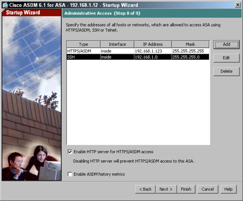
           The Administrative Access page appears.

      20. Set what systems on your network can connect to your ASA to perform management or configuration changes.
 
       Use the following process to add new management interfaces. If you want to use ASDM, you need to select the Enable HTTP Server for HTTPS/ASDM Access check box, whereas the Enable ASDM History Metrics check box saves usage data regarding accessing the ASDM interface.

       In the command line setup, you only have the option to ASDM connections to be made from a single computer. This page allows you to specify additional systems that can perform management of your ASA and the type of connection they make to perform that configuration.


If you add a new management option, the Add Administrative Access Entry dialog box appears. Select your desired options to create the new Administrative Access entry:
  1. Choose HTTP (ASDM), SSH, or Telnet from the Access Type drop-down list.

  2. Choose Inside from the Interface Name drop-down list.

    Inside is typically the most secure interface option, but in some cases, such as if you need to be able to conduct remote administration over the Outside interface, you should be very restrictive in the address from which the administration is performed.

  3. Specify either a specific address from which administration is performed in the IP Address text box or give a network range defined by either an IP address or a Network ID from the Subnet Mask drop-down list.

    Remember, the more restrictive you can be with this configuration, the more secure your ASA is.
  4. Click OK.

    You return to the Administrative Access page.
If you allow your firewall to be administered from the outside interface, you leave yourself open to potentially being compromised by someone you do not know.


      21. Click the Next button.
 
            The summary page of the configuration Start-up Wizard appears, providing a summary of the configuration that you have applied to the system. All these configuration changes are written into the running configuration on the ASA. After the configuration changes are made, you see the standard ASA ASDM management screen. From this interface you can
  • Perform any other configuration changes.

  • Relaunch the Startup Wizard or other wizards.

  • Perform basic monitoring of the ASA via the home page.

  • Perform more detailed monitoring of the ASA and connections that it hosts through the Monitoring pages.

  • Run additional management and troubleshooting tools.

  • Save the current configuration to flash memory.


BGP is a complex, advanced distance Exterior Gateway Protocol (EGP), BGP exchange routing information between Autonomous Systems ( - See more at: http://orbit-computer-solutions.com/BGP.php#sthash.4FLPX5lf.dpuf
BGP (Border Gateway Protocol)

Wednesday, February 18, 2015

Securing Switch Access (All in One)

Conventional network security often focuses more on routers and blocking traffic from the outside. Switches are internal to the organization and designed to allow ease of connectivity, therefore only limited or no security measures are applied.

Switches direct and control much of the data flowing across computer networks.

Network Hierarchy


In a well-formed hierarchical network, there are three defined layers: access, distribution and core. In an enterprise network, each layer provides different functions. Because these layers are not always recognized by their traditional names, the names have been referred to as access or workgroup, distribution or policy, and core or backbone.

Configure Switch Security


    1.    Operating System

If an operating system on a switch is not kept current then the switch may be susceptible to information gathering and network attacks. Attackers find weaknesses in versions of an operating system over time. New security features are added to each new version of an operating system.

Install the latest stable version of the IOS on each Switch.

    2.    Passwords

One password is used for the enable password and the other will later be assigned to the console port.

SWITCH(config)#enable secret  [password]
SWITCH(config)#username admin password [password]

A password should be required to access the console line.  Even the basic user EXEC mode can provide significant information to a malicious user. In addition, the VTY lines must have a password before users can access the switch remotely.

SWITCH(coanfig)#line console 0
SWITCH(config-line)#password cisco
SWITCH(config-line)#login
SWITCH(config-line)#line vty 0 15
SWITCH(config-line)#password cisco
SWITCH(config-line)#login
SWITCH(config-line)#exit

At this stage, the privileged EXEC password is already encrypted. To encrypt the line passwords that you just configured, enter the service password-encryption command in global configuration mode.

SWITCH(config)#service password-encryption

Set the exec-timeout period to 9 minutes or less to disconnect idle connections to the console line on each switch. Do not set the timeout period to zero because on Cisco switches that will disable the timeout. The following example sets the timeout period for the console line to 9 minutes and 0 seconds.

SWITCH(config)# line con 0
SWITCH(config-line)# exec-timeout 9 0

Configure the message-of-the-day (MOTD) using Authorized Access Only as the text. Follow these guidelines:
i.           The banner text is case sensitive. Make sure you do not add any spaces before or after the banner text.
ii.         Use a delimiting character before and after the banner text to indicate where the text begins and ends. The delimiting character used in the example below is %, but you can use any character that is not used in the banner text.
iii.     After you have configured the MOTD, log out of the switch to verify that the banner displays when you log back in.

SWITCH(config)#banner motd %Authorized Access Only%
SWITCH(config)#end
SWITCH#exit

    3.    Network Services

Switches can have a number of network services enabled. Many of these services are typically not necessary for a switch’s normal operation; however if these services are enabled then the switch may be susceptible to information gathering or to network attacks. The characteristics or the poor configuration of the network services on a switch can lead to compromise. Most of these services use one of the following transport mechanisms at Layer 4 of the OSI RM: Transmission Control Protocol (TCP) and User Datagram Protocol (UDP).
If possible, instead of using a network service (e.g., telnet) to perform in-band management of a switch, use out-of-band management (e.g., via the console port) for each switch. Out-of-band management reduces the exposure of configuration information and passwords better than in-band management.

3.1.         Unnecessary Network Services

If possible, disable each unnecessary network service on each switch. The following commands will disable services of concern. In some cases, the commands affect the switch globally, while in other cases the commands affect only a single interface.

Below is an example for the set of interfaces that includes GigabitEthernet 6/1 through 6/3.

SWITCH(config)# interface range gigabitethernet 6/1 – 3

3.1.1.      TCP and UDP Small Servers - TCP/UDP Ports 7, 9, 13, 19

Cisco provides support for “small servers” (e.g., echo, discard, daytime and chargen). Two of these servers, echo and chargen, can be used in denial-of-service attacks against one or more switches. These services can be disabled using the following commands.

SWITCH(config)# no service tcp-small-servers
SWITCH(config)# no service udp-small-servers
3.1.2.      Bootp Server - UDP Port 67

A Cisco switch can act as a bootp server to distribute system images to other Cisco systems. Unless this is an operational requirement, it is best to disable this service with the following command to minimize unauthorized access to the switch’s system image.

Switch(config)# no ip bootp server

3.1.3.      Finger - TCP Port 79

Cisco switches support the finger service, which can provide information about users currently logged onto the switch. Either of the following commands will disable finger service. The first command will replace the second command in future versions of IOS.

Switch(config)# no ip finger
Switch(config)# no service finger

3.1.4.      Configuration Autoload

A Cisco switch can obtain its configuration from a network server via a few methods. These methods are not recommended because configuration information is passed in cleartext during the boot process and can be collected by unauthorized users. Use the following commands to disable these methods.

Switch(config)# no service config
Switch(config)# no boot host
Switch(config)# no boot network
Switch(config)# no boot system

3.1.5.      Packet Assembler/Disassembler (PAD)

PAD enables X.25 connections between network systems. Unless a network requires this capability the PAD service should be disabled with the following command.

Switch(config)# no service pad

3.1.6.      Address Resolution Protocol (ARP)

Normally, ARP messages are confined to a single broadcast domain, but a switch can proxy ARP messages from one domain to another. Unless a switch is required to be an intermediary for ARP requests, this feature should be disabled with the following commands on each interface where it is not required.

Switch(config-if)# no ip proxy-arp
3.1.7.      Internet Control Message Protocol (ICMP) Messages

A Cisco switch can generate automatically three types of ICMP messages: Host Unreachable, Redirect and Mask Reply. The Mask Reply message provides the subnet mask for a particular network to the requestor. An attacker can use these messages to aid in mapping a network. Disabling these messages with the following commands is recommended for each interface and for the Null 0 interface.

Switch(config-if)# no ip unreachables
Switch(config-if)# no ip redirects
Switch(config-if)# no ip mask-reply

The Null 0 interface deserves particular attention. This interface is a packet sink. It is sometimes utilized in denial-of-service attack prevention and all blocked packets are forwarded to this interface. It will generate Host Unreachable messages that could flood the network unless the facility is disabled. Attackers might also be able to use these messages to determine access-control list configuration by identifying blocked packets.

Directed broadcasts allow broadcast messages initiated from different broadcast domains than are locally attached to the switch. For example, attackers have used ICMP directed broadcasts for this purpose. It is recommended that this broadcast capability be turned off, using the following command on each interface.

Switch(config-if)# no ip directed-broadcast

3.2.         Potentially Necessary Network Services

Certain network services may be necessary for the administration of a switch. If in-band management or a specific network service is necessary, then consider the following subsections for configuring network services more securely.

Set up a unique account for each administrator for access to any necessary network service. The following commands present an example that creates an account (e.g., ljones) with a privilege level (e.g., 0). This account is local to the switch only. Privilege level 0 is the lowest level on Cisco switches and allows a very small set of commands. The administrator can go to a higher level (e.g., 15) from level 0 using the enable command.

Switch(config)# username ljones privilege 0
Switch(config)# username ljones secret g00d-P5WD
3.2.1.      Domain Name System (DNS) - TCP Port 53 and UDP Port 53

To specify a DNS server for name resolution, use the ip name-server command. This command can be used to set up to six DNS servers. The following example sets the IP address of 10.1.200.97 as the DNS server.

Switch(config)# ip name-server 10.1.200.97

To enable the DNS-based hostname-to-address translation, use the ip domain-lookup command. This command allows DNS broadcast queries from the switch to be resolved by a DNS server.

Switch(config)# ip domain-lookup

In some cases, the administrator may not want this DNS query capability. For example, if the administrator types a command incorrectly, then the switch may attempt to resolve the mistyped string to an IP address. This attribute can cause undesirable delay. Thus, use the following command to disable the capability if necessary.

Switch(config)# no ip domain-lookup

To specify a default domain name to complete unqualified hostnames, use the ip domain-name command. The following example sets the domain name to test.lab using this command.

Switch(config)# ip domain-name test.lab

3.2.2.      Secure Shell (SSH) - TCP Port 22

If remote access to a switch is necessary, then consider using SSH instead of telnet. SSH provides encrypted connections remotely. However, only IOS versions that include encryption support SSH. Also, to include SSH capability the switch may need to have its IOS updated.

Before using SSH on the switch, the administrator must configure the switch with the following commands: hostname, ip domain-name, and crypto key generate rsa. The following example sets the hostname to Switch.

Switch(config)# hostname Switch

Refer to the previous subsection on DNS for an example using the ip domain-name command.

The crypto key generate rsa command depends on the hostname and ip domain-name commands. This crypto command generates a Rivest, Shamir, Adleman (RSA) key pair, which includes one public RSA key and one private RSA key.
The following example shows this crypto command, including the two parameters, the name for the keys (e.g., switch.test.lab) and the size of the key modulus (e.g., 1024), that are prompted for.

Switch(config)# crypto key generate rsa
The name for the keys will be: switch.test.lab
Choose the size of the key modulus in the range of 360 to 2048 for your General Purpose Keys. Choosing a key modulus greater than 512 may take a few minutes.
How many bits in the modulus[512]? 1024
Generating RSA keys.... [OK].

To restrict SSH access to the switch, configure an extended access-list (e.g., 101) that allows only the administrators’ systems to make these connections and apply this access-list to the virtual terminal lines. Allow only SSH connections to these lines by using the transport input ssh command. Set the privilege level to 0, and set the exec-timeout period to 9 minutes and 0 seconds to disconnect idle connections to these lines. Finally, use the login local command to enable local account checking at login that will prompt for a username and a password.

The following commands show the example configuration for SSH on the virtual terminal lines:

Switch(config)# no access-list 101
Switch(config)# access-list 101 remark Permit SSH access from
administrators’ systems
Switch(config)# access-list 101 permit tcp host 10.1.6.1 any eq 22 log
Switch(config)# access-list 101 permit tcp host 10.1.6.2 any eq 22 log
Switch(config)# access-list 101 deny ip any any log
Switch(config)# line vty 0 4
Switch(config-line)# access-class 101 in
Switch(config-line)# transport input ssh
Switch(config-line)# privilege level 0
Switch(config-line)# exec-timeout 9 0
Switch(config-line)# login local

The login local command cannot be used with AAA. Instead, use the login authentication command.

3.2.3.      Telnet Server - TCP Port 23

If the administrator cannot upgrade the switch to an IOS version with SSH, then restrict telnet access to the switch. Configure an extended access-list (e.g., 102) that allows only the administrators’ systems to make these connections and apply this access-list to the virtual terminal lines. Allow only telnet connections to these lines by using the transport input telnet command. Set the privilege level to 0, and set the exec-timeout period to 9 minutes and 0 seconds to disconnect idle connections to these lines. Finally, use the login local command to enable local account checking at login that will prompt for a username and a password.

The following commands show the example configuration for telnet on the virtual terminal lines.

Switch(config)# no access-list 102
Switch(config)# access-list 102 remark Permit telnet access from
administrators’ systems
Switch(config)# access-list 102 permit tcp host 10.1.6.1 any eq 23 log
Switch(config)# access-list 102 permit tcp host 10.1.6.2 any eq 23 log
Switch(config)# access-list 102 deny ip any any log
Switch(config)# line vty 0 4
Switch(config-line)# access-class 102 in
Switch(config-line)# transport input telnet
Switch(config-line)# privilege level 0
Switch(config-line)# exec-timeout 9 0
Switch(config-line)# login local

The login local command cannot be used with AAA. Instead, use the login authentication command.

3.2.4.      Hyper Text Transfer Protocol (HTTP) - TCP Port 80

An HTTP server is included in IOS to allow remote administration of the switch through a web interface. If web-based administration of the switch is not necessary, then disable the HTTP server using the following command.

Switch(config)# no ip http server

3.2.5.      Simple Network Management Protocol (SNMP) - UDP Ports 161, 162

SNMP is a service used to perform network management functions using a data structure called a Management Information Base (MIB). Unfortunately, SNMP version 1 is widely implemented but not very secure, using only clear-text community strings for access to information on the switch, including its configuration file.

If SNMP is not being used, then executing the following commands will disable the service:

Switch(config)# no snmp-server community
Switch(config)# no snmp-server enable traps
Switch(config)# no snmp-server system-shutdown

Switch(config)# no snmp-server

3.2.6.      Cisco Discovery Protocol (CDP)

CDP provides a capability for sharing system information between Cisco routers, switches and other products. Some of this information includes VLAN Trunking Protocol (VTP) domain name, native VLAN and duplex. If this information is not required for operational needs, then it should be disabled globally and disabled on each interface (e.g., physical, Virtual LAN {VLAN}). To disable CDP globally on a switch, use the no cdp run command. To disable CDP on an interface on a switch, use the no cdp enable command. The following commands provide an example, including how to disable advertising CDP version 2 on a switch.

Switch(config)# no cdp run
Switch(config)# no cdp advertise-v2
Switch(config)# interface range fastethernet 0/1 - 24
Switch(config-if)# no cdp enable

If CDP is necessary, then it needs to be enabled globally and enabled only on interfaces where it is necessary. The following commands provide an example of disabling CDP on one interface while enabling CDP on another interface.

Switch(config)# cdp run
Switch(config)# interface VLAN10
Switch(config-if)# no cdp enable
Switch(config)# interface VLAN101
             Switch(config-if)# cdp enable  

4.    Port Security

Layer 2 interfaces on a Cisco switch are referred to as ports. A switch that does not provide port security allows an attacker to attach a system to an unused, enabled port and to perform information gathering or attacks. A switch can be configured to act like a hub, which means that every system connected to the switch can potentially view all network traffic passing through the switch to all systems connected to the switch. Thus, an attacker could collect traffic that contains usernames, passwords or configuration information about the systems on the network.

Port security limits the number of valid MAC addresses allowed on a port. All switch ports or interfaces should be secured before the switch is deployed. In this way the security features are set or removed as required instead of adding and strengthening features randomly or as the result of a security incident. Note that port security cannot be used for dynamic access ports or destination ports for Switched Port Analyzer. Still, use port security for active ports on the switch as much as possible.

The following examples show the commands to shut down a single interface or a range of interfaces:
Single interface:
Switch(config)# interface fastethernet 0/1
Switch(config-if)# shutdown

Range of interfaces:
Switch(config)# interface range fastethernet 0/2 - 8
Switch(config-if-range)# shutdown

The administrator can enable aging for statically configured MAC addresses on a port using the switchport port-security aging static command. The aging time command (e.g., switchport port-security aging time time) can be set in terms of minutes. Also, the aging type command can be set for inactivity (e.g., switchport port-security aging type inactivity), which means that the addresses on the configured port age out only if there is no data traffic from these addresses for the period defined by the aging time command. This feature allows continuous access to a limited number of addresses.

The following example shows the commands for restricting a port statically on a Catalyst 3550 switch:

Switch(config-if)# switchport port-security
Switch(config-if)# switchport port-security violation shutdown
Switch(config-if)# switchport port-security maximum 1
Switch(config-if)# switchport port-security mac-address 0000.0200.0088
Switch(config-if)# switchport port-security aging time 10
Switch(config-if)# switchport port-security aging type inactivity

To restrict a port dynamically on a Catalyst 3550 switch use the following commands. Note that the aging commands cannot be used with sticky MAC addresses.

Switch(config-if)# switchport port-security
Switch(config-if)# switchport port-security violation shutdown
Switch(config-if)# switchport port-security maximum 1
Switch(config-if)# switchport port-security mac-address sticky

Note that when a port security violation occurs, the port will immediately become error-disabled and its LED will turn off. The switch also sends an SNMP trap, logs a syslog message and increments the violation counter. When a port is in the error-disabled state, the administrator can bring it out of this state by entering the errdisable recovery cause psecure-violation global configuration command or by entering the shutdown and no shutdown interface configuration commands.

The following example creates a strict security macro called unused to secure the ports, or interfaces, on a 3550 switch:
Switch(config)# macro name unused
macro description unused
shutdown
description *** UNUSED Port ***
no ip address
switchport
# Set secure defaults for access mode
switchport mode access
switchport access vlan 999
switchport nonegotiate
# Set secure defaults for trunking mode
switchport trunk encapsulation dot1q
switchport trunk native vlan 999
switchport trunk allowed vlan none
# Only learn source MAC addresses
switchport block multicast
switchport block unicast
# Enable MAC control and set secure options
switchport port-security
switchport port-security maximum 1
switchport port-security aging time 10
switchport port-security aging type inactivity
# Apply any switch-wide access-lists
ip access-group ip-device-list in
mac access-group mac-device-list in
# Set secure defaults for misc. flags and protocols
mls qos cos override
dot1x port-control force-unauthenticated
storm-control broadcast level 0.00
storm-control multicast level 0.00
storm-control unicast level 0.00
no cdp enable
# Default Spanning-tree to secure host settings
spanning-tree portfast
spanning-tree bpdufilter enable
spanning-tree bpduguard enable
spanning-tree guard root

After creating this strict security macro, unused, apply the macro to all switch ports as a secure baseline with the following commands:

Switch(config)# interface range fasteth0/1 – 24 , giga0/1 – 2
Switch(config-if-range)# macro apply unused

    5.    System Availability

Many attacks exist and more are being created that cause denial of service, either partially or completely, to systems or networks. Switches are just as susceptible to these attacks. These attacks focus on making resources (e.g., system processor, bandwidth) unavailable.
The following countermeasures will mitigate the vulnerabilities to system availability on each switch:

·         To prevent fast flooding attacks and to guarantee that even the lowest priority processes get some processor time use the scheduler interval command. The following example sets the maximum time before running the lowest priority process to 500 milliseconds access.

Switch(config)# scheduler interval 500

Another way to guarantee processor time for processes is to use the scheduler allocate command. This command sets the interrupt time and the process time.

The following example makes 10 percent of the processor available for process tasks, with an interrupt time of 4000 microseconds and a process time of 400 microseconds.

Switch(config)# scheduler allocate 4000 400

·         Use the following command on each interface to turn Flow Control off.

Switch(config-if)# flowcontrol receive off

·      UDLD should be disabled globally and on every interface where it is not required. To  disable UDLD globally use the following command.

Switch(config)# no udld enable

To disable UDLD on each interface use one of the following commands, depending on the switch model and IOS version.

Switch(config-if)# no udld port
Switch(config-if)# udld disabled

·    To help prevent the SYN Flood attack the administrator can set the amount of time the switchwill wait while attempting to establish a TCP connection. The following command sets the wait time to 10 seconds.
        Switch(config)# ip tcp synwait-time 10

·     In order for voice traffic to have priority through a network it must be easy to determine which packets are voice, even if the voice signaling and data are encrypted. However, anyone with a network analyzer can also easily pick out the voice traffic. This additional risk must be considered in order to decide if Quality of Service (QoS) parameters will be configured for voice traffic.

The following command will turn on QoS features:

Switch(config)# mls qos

The following command will force best effort priority for an untrusted system.

Switch(config-if)# mls qos cos 0
Switch(config-if)# mls qos cos override

The following command will accept the priority assigned by a trusted system (e.g., voice gateway).

Switch(config-if)# mls qos trust dscp

The following commands will accept the priority assigned by an IP Phone but will force best effort priority for any attached computer.

Switch(config-if)# mls qos trust dscp
Switch(config-if)# mls qos trust device cisco-phone
Switch(config-if)# switchport priority extend cos 0

Isolate voice traffic in separate subnets using VLANs, and control the interactions between voice and data subnets.

     6.    Virtual Local Area Networks

A Virtual Local Area Network (VLAN) is a broadcast domain. All members of a VLAN receive every broadcast packet sent by members of the same VLAN, but they do not receive packets sent by members of a different VLAN. All members of a VLAN are grouped logically into the same broadcast domain independent of their physical location. Adding, moving or changing members is achieved via software within a switch. Routing is required for communication among members of different VLANs.

The next subsections describe the vulnerabilities and corresponding countermeasures for the following areas: VLAN 1, Private VLAN, VTP, Trunk Auto-Negotiation, VLAN Hopping and Dynamic VLAN Assignment.
6.1.         VLAN1

Cisco switches use VLAN 1 as the default VLAN to assign to their ports, including their management ports. Additionally, Layer 2 protocols, such as CDP and VTP, need to be sent on a specific VLAN on trunk links, so VLAN 1 was selected. In some cases, VLAN 1 may span the entire network if not appropriately pruned. It also provides attackers easier access and extended reach for their attacks.

Do not use VLAN 1 for either out-of-band management or in-band management.
To provide out-of-band management that separates management traffic from user traffic, use the following commands as an example.

Create the out-of-band management VLAN.

Switch(config)# vlan 6
Switch(config-vlan)# name ADMINISTRATION-VLAN

Create a management IP address and restrict access to it. Also, enable the interface.

Switch(config)# no access-list 10
Switch(config)# access-list 10 permit 10.1.6.1
Switch(config)# access-list 10 permit 10.1.6.2
Switch(config)# interface vlan 6
Switch(config-if)# description ADMIN-VLAN
Switch(config-if)# ip address 10.1.6.121 255.255.255.0
Switch(config-if)# ip access-group 10 in
Switch(config-if)# no shutdown

Assign the management VLAN to the dedicated interface.

Switch(config)# interface fastethernet 4/1
Switch(config-if)# description Out-Of-Band Admin
Switch(config-if)# switchport mode access
Switch(config-if)# switchport access vlan 6
Switch(config-if)# no shutdown

Ensure all trunk ports will not carry the management VLAN (e.g., 6).

Switch(config)# interface range gigabitethernet 6/15 - 16
Switch(config-if)# switchport trunk allowed vlan remove 6

Assigned the following name for VLAN 1.
Switch# vlan 1
Switch(vlan)# name *** DEFAULT VLAN - Do NOT Use! ***

Assign all inactive interfaces to an unused VLAN other than VLAN 1 and shut down these interfaces. Note that unused VLANs are not routable.

Switch# vlan 999
Switch(vlan)# name *** BIT BUCKET for unused ports ***
Switch(vlan)# shutdown
Switch(vlan)# exit
Switch(config)# interface range fastethernet 5/45 - 48
Switch(config-if)# switchport mode access
Switch(config-if)# switchport access vlan 999
Switch(config-if)# shutdown

Assign all interfaces to VLANs other than VLAN 1.

Switch(config)# interface fastethernet 0/1
Switch(config-if)# switchport mode access
Switch(config-if)# switchport access vlan 999

6.2.         Private VLAN (PVLAN)

In certain instances where similar systems do not need to interact directly, PVLANs provide additional protection. A primary PVLAN defines the broadcast domain with which the secondary PVLANs are associated. The secondary PVLANs may either be isolated PVLANs or community PVLANs. Hosts on isolated PVLANs communicate only with promiscuous ports, and hosts on community PVLANs communicate only among themselves and with associated promiscuous ports. This configuration provides fine-grained Layer 2 isolation control for each system.

A configuration with multiple servers on a single VLAN should use PVLANs for Layer 2 separation among the servers. Routers should be on promiscuous ports and servers on an isolated PVLAN. Only servers that need to communicate directly with other servers should be on a community PVLAN. Implement VACLs on the primary PVLAN to filter traffic originated by and routed to the same segment.

The following example creates a PVLAN with an NTP server on a promiscuous port and two isolated servers.

Switch# vlan 200
Switch(vlan)# name SERVERS-PRIVATE
Switch(vlan)# private-vlan primary
Switch(vlan)# private-vlan association 201
Switch# vlan 201
Switch(vlan)# name SERVERS-ISOLATED
Switch(vlan)# private-vlan isolated
Switch(config)# interface GigabitEthernet6/1
Switch(config-if)# description SERVER 1
Switch(config-if)# switchport private-vlan host-association 200 201
Switch(config-if)# switchport mode private-vlan host
Switch(config-if)# no shutdown
Switch(config)# interface GigabitEthernet6/2
Switch(config-if)# description SERVER 2
Switch(config-if)# switchport private-vlan host-association 200 201
Switch(config-if)# switchport mode private-vlan host
Switch(config-if)# no shutdown
Switch(config)# interface GigabitEthernet6/6
Switch(config-if)# description SERVER NTP Server
Switch(config-if)# switchport mode private-vlan promiscuous
Switch(config-if)# switchport private-vlan mapping 200 201
Switch(config-if)# no shutdown

6.3.         Virtual Trunking Protocol (VTP)

VTP is a Cisco-proprietary Layer 2 messaging protocol used to distribute VLAN configuration information over trunks. VTP allows the addition, deletion and renaming of VLANs on a network-wide basis, which allows switches to have a consistent VLAN configuration within a VTP management domain. All switches in the same management domain share their VLAN information, and a switch may participate in only one VTP management domain.

A switch may be in one of three VTP modes: server, transparent and client.

By default, switches share VLAN information without any authentication. Thus, inaccurate VLAN settings can propagate throughout a VTP domain. Compounding this problem, switches come with VTP in server mode by default, and a server with a higher configuration revision number in its VTP database supersedes one with a lower number. It is entirely possible for a single switch, which has undergone a sufficient number of VTP reconfigurations, to completely overwrite or eliminate all VLAN assignments of an operational network by just connecting it to the network. Such an attack would not necessarily have to be malicious; simply moving a lab switch to an operational network could have this effect.
It is clear that VTP simplifies administration, particularly where large numbers of VLANs are deployed. Nevertheless, VTP is sufficiently dangerous that its use is discouraged. If possible, turn off VTP by using the following commands.

Switch(config)# no vtp mode
Switch(config)# no vtp password
Switch(config)# no vtp pruning

If VTP is necessary, then consider the following settings. Set up VTP management domains appropriately. All switches in the same management domain share their VLAN information. A switch can only participate in one VTP management domain. Use the following command as an example to set the VTP management domain.

Switch(config)# vtp domain test.lab

Assign a strong password to the VTP management domain. All switches within the domain must be assigned the same password. This prevents unauthorized switches from adding themselves to the VTP management domain and passing incorrect VLAN information. Use password protection on VTP domains as shown in the command in the following example.

Switch(config)# vtp password g00d-P5WD

Enable VTP pruning and use it on appropriate ports. By default, VLANs numbered 2 through 1000 are pruning-eligible.

Switch(config)# vtp pruning

Set VTP to transparent mode with the following command.

Switch(config)# vtp transparent

6.4.         Trunk Auto-Negotiation

A trunk is a point-to-point link between two ports, typically on different network systems, that aggregates packets from multiple VLANs. Cisco implements two types of trunks: IEEE 802.1q, which is an open standard; and ISL, which is a Cisco proprietary standard.

A port may use the Dynamic Trunking Protocol (DTP) to automatically negotiate which trunking protocol it will use, and how the trunking protocol will operate. By default, a Cisco Ethernet port's default DTP mode is "dynamic desirable", which allows the port to actively attempt to convert the link into a trunk. Even worse, the member VLANs of the new trunk are all the available VLANs on the switch. If a neighboring port's DTP mode becomes "trunk", "dynamic auto", or "dynamic desirable", and if the two switches support a common trunking protocol, then the line will become a trunk automatically, giving each switch full access to all VLANs on the neighboring switch. An attacker who can exploit DTP may be able to obtain useful information from these VLANs.

Do not use DTP if possible. Assign trunk interfaces to a native VLAN other than VLAN 1.

Switch(config)# interface fastethernet 0/1
Switch(config-if)# switchport mode trunk
Switch(config-if)# switchport trunk native vlan 998

Put non-trunking interfaces in permanent non-trunking mode without negotiation.

Switch(config)# interface fastethernet 0/1
Switch(config-if)# switchport mode access
Switch(config-if)# switchport nonegotiate

Put trunking interfaces in permanent trunking mode, without negotiation.

Switch(config)# interface fastethernet 0/1
Switch(config-if)# switchport mode trunk
Switch(config-if)# switchport nonegotiate

Specifically list all VLANs that are part of the trunk.

Switch(config)# interface fastethernet 0/1
Switch(config-if)# switchport trunk allowed vlan 6, 10, 20, 101

Use a unique native VLAN for each trunk on a switch.

Switch(config)# interface fastethernet 0/1
Switch(config-if)# switchport trunk native vlan 998

Switch(config)# interface fastethernet 0/2
Switch(config-if)# switchport trunk native vlan 997

6.5.         VLAN Hopping

In certain situations it is possible to craft a packet in such a way that a port in trunking mode will interpret a native VLAN packet as though it were from another VLAN, allowing the packet to become a member of a different VLAN. This technique is known as VLAN hopping. Using VLAN hopping, a malicious intruder who has access to one local network might inject packets into another local network in order to attack machines on the target network.

Disable CDP, VTP and DTP on each switch if possible. Assign a shutdown VLAN as the 'native' VLAN of each of the trunks, and do not use this VLAN for any other purpose.
Switch(config)# interface fastethernet 0/1
Switch(config-if)# switchport trunk native vlan 998
Switch(config-if)# no cdp enable

Restrict the VLANs on a trunk to only those that are necessary for that trunk, as described in the Trunk Auto-Negotiation subsection previously. 

7.    Spanning Tree Protocol

Spanning Tree Protocol (STP), also known as 802.1d, is a Layer 2 protocol designed to prevent loops within switched networks. Typically, STP goes through a number of states (e.g., block, listen, learn, and forward) before a port is able to pass user traffic.

A vulnerability associated with STP is that a system within the network can actively modify the STP topology. There is no authentication that would prevent such an action. The bridge ID, a combination of a two-byte priority and a six-byte MAC address, determines the root bridge within a network.

7.1.         STP Portfast Bridge Protocol Data Unit (BPDU) Guard

The STP Portfast BPDU Guard allows network administrators to enforce the STP topology on ports enabled with Portfast. Systems attached to ports with the Portfast BPDU Guard enabled will not be allowed to modify the STP topology. Upon reception of a BPDU message, the port is disabled and stops passing all network traffic.

This feature can be enabled both globally and individually for ports configured with Portfast. By default, STP BPDU guard is disabled. The following command is used to globally enable this feature on a Cisco 3550 series switch.

Switch(config)# spanning-tree portfast bpduguard default

Use the following command to verify the configuration.

Switch> show spanning-tree summary totals

To enable this feature at the interface level on a Cisco 3550 series switch, use the following command.

Switch(config-if)# spanning-tree bpduguard enable

When STP BPDU guard disables a switch port, it can be configured to recover automatically, or it can be manually re-enabled by a network administrator. The following commands can be used to configure a port to automatically recover when placed in a disabled state.

In the example below, a port placed in an error-disabled state will recover after 400 seconds.
Switch(config)# errdisable recovery cause bpduguard
Switch(config)# errdisable recovery interval 400

7.2.         STP Root Guard

The STP Root Guard feature is another mechanism used to protect the STP topology. Unlike the BPDU Guard, STP Root Guard allows participation in STP as long as the attached system does not attempt to become the root. If the Root Guard is activated, then the port recovers automatically after it quits receiving the superior BPDUs that would make it the root. Root Guard can be applied to one or more ports on edge switches and on internal switches on a network. In general, apply this feature to those ports on each switch that should not become the root.
The following command is used within the interface configuration mode to enable STP Root Guard on the Cisco 3550 series switch.

Switch(config-if)# spanning-tree guard root

     8.    Access Control Lists

A switch with either no access control list (ACL) or a permissive ACL applied to its interfaces allows broad access for TCP/IP connections (e.g., FTP, telnet, DNS, HTTP, SNMP, ICMP) through the switch to any system (e.g., critical server) on the protected network.

In preparation for implementing ACLs, categorize systems attached to the switches into groups that use the same network services. Grouping systems this way helps reduce the size and complexity of associated ACLs.

ACLs can permit or deny each packet based on the first access control statement that the packet matches. There are different types of access control lists: Port Access Control List (PACL), Router Access Control List (RACL) and VLAN Access Control List (VACL).

8.1.         Port Access Control List (PACL)

PACLs are used to restrict the packets allowed into a given port. There are two types of PACLs, IP PACLs based on IP access lists and MAC PACLs based on MAC access lists. IP PACLs only filter packets with an IP ethertype. Creating a standard or extended IP access list and applying the access list to a switchport interface is all that is required to implement IP PACLs.

Given an IOS that supports Unicast MAC Filtering, the following commands are an example of using PACLs to restrict port access to one specific MAC address and IP access to one specific IP address from that MAC address.

Switch(config)# mac access-list extended host-mac
Switch(config-ext-macl)# permit host 0000.0101.0011 any
Switch(config-ext-macl)# exit
Switch(config)# ip access-list extended host-ip
Switch(config-ext-nacl)# permit ip host 10.1.101.11 any
Switch(config-ext-nacl)# exit
Switch(config)# interface fa0/2
Switch(config-if)# mac access-group host-mac in
Switch(config-if)# ip access-group host-ip in

Another way to use PACLs is in place of static MAC addresses and port security. Allowed MAC and IP addresses could be pooled and viewed from a switch wide perspective. Consider the following commands as an example of this pooled addressing security.

Switch(config)# mac access-list extended mac-device-list
Switch(config-ext-macl)# permit host 0000.0101.0011 any
Switch(config-ext-macl)# permit host 0000.0101.0012 any
Switch(config-ext-macl)# permit host 0000.0101.0013 any
Switch(config-ext-macl)# permit host 0000.0101.0014 any
Switch(config-ext-macl)# permit host 0000.0010.0003 any
Switch(config-ext-macl)# permit host 0000.0020.0005 any

Switch(config)# ip access-list extended ip-device-list
Switch(config-ext-nacl)# permit ip host 10.1.101.11 any
Switch(config-ext-nacl)# permit ip host 10.1.101.12 any
Switch(config-ext-nacl)# permit ip host 10.1.101.13 any
Switch(config-ext-nacl)# permit ip host 10.1.101.14 any
Switch(config-ext-nacl)# permit ip host 10.1.10.3 any
Switch(config-ext-nacl)# permit ip host 10.1.20.5 any

Switch(config)# interface range fa0/1 - 24
Switch(config-if-range)# ip access-group ip-device-list in
Switch(config-if-range)# mac access-group mac-device-list in

8.2.         Router Access Control List (RACL)

A RACL can restrict packets into or out of a given Layer 3 interface. A RACL is configured and applied identically to a router ACL, except a RACL is applied to a VLAN interface.

Switch(config)# access-list 1 remark Simple Example
Switch(config)# access-list 1 permit any
Switch(config)# interface vlan 6
Switch(config-if)# ip access-group 1 in
8.3.         VLAN Access Control List (VACL)

VACLs use VLAN Maps that are configured like route-maps on routers. VLAN Maps can be applied to filter all traffic into, through and out of a specific VLAN. The same VLAN Map filters bridged, inbound and outbound packets for the VLAN. The following example will block all TCP packets from VLAN 6 while allowing all other packets through.

Switch(config)# no access-list 101
Switch(config)# access-list 101 remark Simple TCP Example
Switch(config)# access-list 101 permit tcp any any
Switch(config)# vlan access-map vlan6-map 10
Switch(config-access-map)# match ip address 101
Switch(config-access-map)# action drop
Switch(config-access-map)# exit
Switch(config)# vlan access-map vlan6-map 20
Switch(config-access-map)# action forward
Switch(config-access-map)# exit
Switch(config)# vlan filter vlan6-map vlan-list 6

    9.    Logging and Debugging

Poor configuration and monitoring of the logging and debugging capabilities on a switch may lead to inadequate information when an attack occurs against the switch or the networks connected to it. Problems can also arise if logging is enabled but not managed properly. Log files maintained on the switch are at risk of being overwritten since there is limited space on the switch itself to store logging information. Also, logs that reside on the switch may be subject to erasure or compromise by an attacker.

9.1.         Logging Configuration

Enable logging on each switch with the following command.

Switch(config)# logging on

The following command shows how to direct logs to a log host. Note that IOS can support multiple log hosts; the administrator just uses the logging <IP address> command for each log host on the network.

Switch(config)# logging 10.1.6.89

For each access-list on each switch, set the log keyword for each access-list statement that denies network traffic through the switch or that allows or denies access to the switch itself. The following command shows an example access-list statement with the log keyword.
Switch(config)# access-list 101 deny ip any any log

The administrator needs to configure the trap level for syslog on each switch to determine which logs will be sent to the log host. The following shows the command to set the trap level, along with description of the various trap levels.

Switch(config)# logging trap level

where level is the number or keyword that corresponds to one of the following eight syslog severity levels


The syslog facility can also be set on the switch. Use the following command to do this.

Switch(config)# logging facility facility-type

where facility-type is one of the following keywords
local0                   local3              local6
local1                   local4              local7 (default)
local2                   local5              syslog
Each system status message logged in the system logging process has a sequence reference number applied. The following command makes the sequence number for each message visible by displaying the number with the message.
Switch(config)# service sequence-numbers

9.2.         Time Information

Configure each switch and each log host to point to at least two different reliable timeservers to ensure accuracy and availability of time information and to protect against denial-of-service attacks against a single timeserver.
For example, the following command designates the addresses of a timeserver and the interface for the source address to be used in the NTP messages sent from the switch to the timeserver.

Switch(config)# ntp server 10.1.200.94 source Loopback0 prefer

Cisco switches offer support for NTP authentication to prevent accidental or malicious changes of the system clock. For example, the following commands enable NTP authentication, create an authentication key (e.g., aGr8key!) associated with a key number (e.g., 42), identify that key number as required for authentication, and configure an NTP server with associated key.

Switch(config)# ntp authenticate
Switch(config)# ntp authentication-key 42 md5 aGr8key!
Switch(config)# ntp trusted-key 42
Switch(config)# ntp server 10.1.200.94 key 42 prefer

Note that when a switch is configured to use NTP for time synchronization, the switch also becomes an NTP server. Unless the switch is meant to act as an NTP server on the network, NTP should be disabled on all interfaces that do not pass NTP traffic.

Switch(config-if)# ntp disable

In addition to referencing timeservers, the switch should include the date and the time when a log message or a debug message is sent. To reflect the date and the time in these messages, timestamps need to be set on the switch. Configure timestamps for logging and debugging with the following commands.

Switch(config)# service timestamp log datetime msec localtime show-timezone
Switch(config)# service timestamp debug datetime msec localtime show-timezone.

where
datetime– Provides the date and the time
msec– Include milliseconds with the time
localtime– Shows time in terms of the local time
show-timezone– Indicates the time zone

If the switches being managed are in multiple timezones, then use Greenwich Mean Time (GMT) for the timezone for all the switches. Otherwise, use the local timezone on the switch. The following commands show an example of setting the timezone for Eastern Standard Time (e.g., EST) and setting the switch to automatically change for daylight savings time (e.g., EDT).
Switch(config)# clock timezone EST –5
Switch(config)# clock summer-time EDT recurring

    10.  Authentication, Authorization, and Accounting

Typically, remote administrator access to a Cisco switch requires a password but no username. There is no accountability for which administrator has connected to the switch. Also, no mechanism is set by default for what an administrator is allowed to do.

Cisco provides three security mechanisms called Authentication, Authorization and Accounting (AAA) that can address these vulnerabilities. Configure AAA on a switch in conjunction with a security server.

Use of AAA with a security server provides the security mechanisms described below.

·    Authentication– This mechanism identifies remote and local users before granting access to the switch.
·   Authorization– This mechanism controls access to remote services based on defined attributes associated with the authenticated user.
·    Accounting– This mechanism provides a secure logging capability for recording services accessed by a user as well as a user’s bandwidth consumption
AAA allows for security servers to use three types of protocols: RADIUS, TACACS+ and Kerberos.

This setting is important, especially if the administrator is configuring the switch remotely.
The following command shows an example of how to create a local user, including the username (e.g., ljones) with a privilege level (e.g., 0) and a password (e.g., g00d-P5WD) that will be MD5-encrypted.

Switch(config)# username ljones privilege 0 secret g00d-P5WD

To enable AAA, use the following command.

Switch(config)# aaa new-model

Specifying a security server or set of security servers can be done using the following commands for TACACS+ and RADIUS:

{tacacs-server | radius-server} host ip-address
{tacacs-server | radius-server} key key

One important difference to note about using Kerberos, versus RADIUS or TACACS+, is that additional configuration is required to allow the switch to communicate with the key distribution center (KDC).
10.1.    Authentication

It is necessary to create a login authentication method list(s) (specifying which types of security server protocols will be used and in what order). The following shows the syntax for the command to enable authentication at login at the switch, using either the default list or a custom list and using authentication methods.

aaa authentication login {default | list-name } method1 [method2...]

where the methods include the following:
group radius: uses all RADIUS servers listed
group tacacs+: uses all TACACS+ servers listed
group group-name: uses servers defined by group-name (RADIUS or TACACS+)
krb5: uses Kerberos

An example for configuring a switch to provide TACACS+ authentication using a group name of aaa-admin-servers is the following:

Switch(config)# aaa group server tacacs+ aaa-admin-servers
Switch(config)# aaa authentication login default group aaa-admin-servers

The switch can provide a local login method if for some reason the AAA server is unavailable. It will not allow a user that has been denied access by the AAA server to login using the local authentication mechanism.

The following example shows the use of local as a fallback.

Switch(config)# aaa authentication login aaa-fallback group aaa-admin-servers local

The last step is to apply the authentication method list(s) to the desired lines. The following shows the syntax for the command to enable authentication services to a specific line or a group of lines, applying either the default list or a custom list.

login authentication {default | list-name}

The following example would apply the named list, aaa-fallback, to the console line:

Switch(config)# line con 0
Switch(config-line)# login authentication aaa-fallback

10.2.    Authorization
Similar to authentication, configuring authorization requires the security administrator to define method lists. The following shows the syntax for the command to enable authorization of user access to systems on a network, using either the default list or a custom list and using:

aaa authorization {auth-proxy | network | exec | commands level | reverse-access | configuration | ipmobile} {default | list-name} method1 [method2...]

Recommended authorization types include enabling authorization for the following:

auth-proxy: security policies are applied on a per-user basis
network: service requests
exec: initiation of an EXEC session
commands level: EXEC command execution at specified levels
reverse-access: reverse telnet session
configuration: download configurations from security server
ipmobile: IP Mobile services

An example of configuring a switch to provide TACACS+ authorization, using the aaa-admin-servers group for EXEC and privileged EXEC commands, is the following:

Switch(config)# aaa authorization exec default group aaa-admin-servers
Switch(config)# aaa authorization commands 15 aaa-config group aaa-admin-servers if authenticated

Applying named authorization lists is the final authorization configuration step. The following shows the syntax for the command to enable authorization services to a specific line or a group of lines.

authorization {arap | commands level | exec | reverse-access} {default | list-name}

To enable authorization services to the console line for commands at privilege level 15 (e.g., commands 15) with an authorization list (e.g., aaa-config), the administrator would use the following example:

Switch(config)# line con 0
Switch(config-line)# authorization commands 15 aaa-config

10.3.    Accounting

The final piece of AAA to configure is accounting. Cisco switches support accounting records only for TACACS+ and RADIUS security servers. The following shows the syntax for the command to enable accounting of requested services for security purposes when using RADIUS or TACACS+.
aaa accounting {system | network | exec | connection | commands level} {default | list-name } {start-stop | stop-only | none} [method1 [method2...]]

The five types of accounting that can be specified include the following:

System: information for all system events (no support for named lists, must be default)
Network: information on all network service requests
Exec: information on user EXEC terminal sessions
Connection: information on all outbound connections
Commands level: information about all EXEC commands, at a certain privilege level, that are issued.

To control the amount of accounting records for events specified by a method list, use the following:

start-stop: notices begin at start of event and continue until the end of the event
stop-only: send only a stop notice related to the event
none: no accounting

It is recommended that accounting be enabled for all five types, in particular accounting for level 15 commands. The following example enables all five types and uses the default accounting method, start-stop:

Switch(config)# aaa accounting exec default start-stop group aaa-admin-servers
Switch(config)# aaa accounting commands 15 default start-stop group aaa-admin-servers
Switch(config)# aaa accounting network default start-stop group aaa-admin-servers
Switch(config)# aaa accounting connection default start-stop group aaaadmin-servers
Switch(config)# aaa accounting system default start-stop group aaaadmin-servers

The following shows the syntax for the command to enable accounting services to a specific line or a group of lines:

accounting {arap | commands level | exec | connection} {default | listname}

To enable accounting services to the console line for commands at privilege level 15 (e.g., commands 15) and for system-level events (e.g., exec), the administrator would use the following example:

Switch(config)# line con 0
Switch(config-line)# accounting commands 15 default
Switch(config-line)# accounting exec default

To specify when accounting records are sent to security servers, enable interim accounting records.
Switch(config)# aaa accounting update {newinfo | periodic minutes}

By default, Cisco switches do not generate accounting records for failed login authentication attempts when accounting is enabled. To enable these accounting records, use the following command.

Switch(config)# aaa accounting send stop-record authentication failure

10.4.    802.1X Port-Based Authentication

The IEEE 802.1X standard is a port-based access control and authentication protocol. Although the implementation of this standard is still evolving, it is currently available on many of Cisco’s switches. It forces a client that is connected to a switch port to authenticate to a server, such as Cisco’s Access Control Server, before gaining access to a network. The client must be running 802.1X compliant software, which is available on certain operating systems (e.g., Windows XP).

The following example enables 802.1X on a Cisco IOS switch on the interface Ethernet 1/0:

Switch(config)# aaa authentication dot1x default group radius
Switch(config)# dot1x system-auth-control
Switch(config)# interface Ethernet 1/0
Switch(config-if)# dot1x port-control auto


Switch(config-if)# dot1x host-mode single-host